

![]()
Guilhem MOLLON
guilhem.mollon@insa-lyon.fr
Associate Professor
National Institute for Applied Sciences of Lyon
PhD, Civil Engineering, INSA Lyon
HDR, INSA Lyon
![]()
Guilhem MOLLON
guilhem.mollon@insa-lyon.fr
Associate Professor
National Institute for Applied Sciences of Lyon
PhD, Civil Engineering, INSA Lyon
HDR, INSA Lyon
A large number of deterministic models exist in scientific literature for the study of the face stability of pressrized tunnels. Numerical models mak it possible to obtain both a satisfactory estimate of the critical collapse and blow-out pressures, and the failure shapes corresponding to the two failure modes. The study of several models programmed in the software Flac3D demonstrates the importance of the fineness of the mesh and of the procedure of determination of the critical pressure. Computation times involved in an accurate determination of such a pressure prevent the use of such 3D model in a probabilistic framework with current conventional computationnal means, but these models remain very useful fo the validation of simpler and less costly models. Besides, they make it possible to investigate the differences of failure shapes that may appear between diffrent types of soils.
Numerical models are also suitable for the study of ground movements induced by a pressurized excavation. The model presented hereafter proposes a moderately complex simulation of the different phenomena which occur around a tunnel boring machine during excavation. It provides not only the maximal ground settlement, but also several other quantities (slopes, horizontal deformations, etc.) that are interesting because of their possible impact on constructions existing at the ground surface.
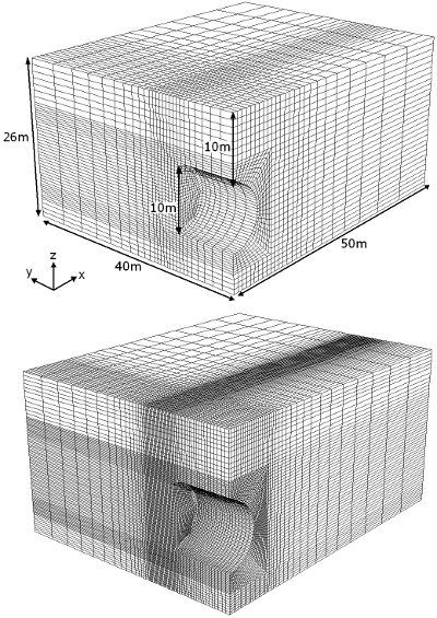
Figure 1. Numerical models for the analysis of the face stability of a pressurized tunnel, with two mesh finenesses.
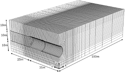
Figure 4. Numerical model for the analysis of the ground movements induced by a pressurized excavation.
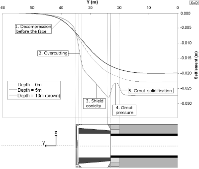
Figure 6. Vertical settlements observed after simulation. The influence of each source of settlement clearly appears.
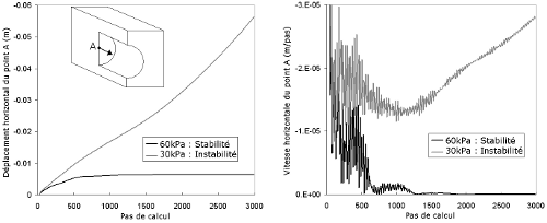
Figure 2. Procedure of estimation of the critical collapse pressure. For a given applied pressure, the state of stability is determined by studying the displacement and the velocity of extrusion of the tunnel face. The critical pressure in computed by successive bracketting using a bisection process.
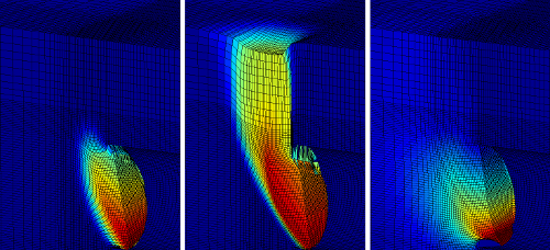
Figure 3. Failure shapes for different types of soils : from left to right, associated frictional soil, non-dilative frictional soil, purely cohesive soil. The differences in failure shape are very clear: frictional soils exhibit localized shear bands between the moving block and the soil at rest (with or without "chimney", depending on the soil dilatancy), and purely cohesive soils exhibit a continuous deformation field behind the tunnel face.
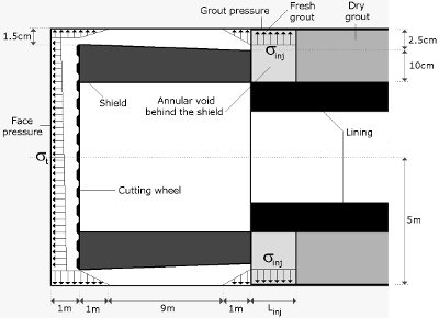
Figure 5. Principles of the model, accounting for the retaining face pressure, overcutting, slurry migration around the shield, shield conicity, grout pressure behind the shield, and grout solidification.
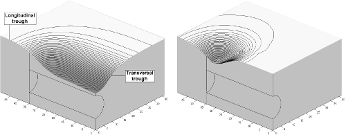
Figure 7. 3D settlement troughs ; left, total settlement ; right, instantaneous settlement related to the latest excavation stage (vertical scale dilated by a factor 10).